While hardness testing gives only a semi-quantitative indication of the resistance to plastic deformation, the outcome of an indentation operation (ie the size and shape of the residual indent) does depend in a sensitive way on the (true) stress-strain curve of the material, potentially over a large range of plastic strain. Extracting only a single measurement of the indent diameter (while simple experimentally) exploits only a minute proportion of the information incorporated into this residual profile. Measurement of the full profile now forms the basis of a new methodology for obtaining complete (true) stress-strain curves from indentation experiments. This is termed indentation plastometry
Limitations of Uniaxial Testing
Before explaining the procedure in detail, it should perhaps be emphasized that, even with conventional (uniaxial) tension or compression testing, it is not necessarily straightforward to obtain the correct true stress – true strain relationship. Of course, it is a simple matter to convert nominal stress and nominal strain to true values. However, this is based on the assumption that the sample is deforming uniformly (within the gauge length) throughout the test. In tension, depending on work hardening characteristics, some necking could be taking place – perhaps from a very early stage and quite possibly without it being at all apparent by simply looking at the sample during the test. This will invalidate the standard conversion of nominal stresses and strains to true values. Similarly, in compression testing there is likely to be at least some frictional resistance to interfacial sliding, and hence a degree of barrelling. Again, this invalidates the standard procedure for obtaining the true stress – true strain relationship (although the effect may be relatively small).
How can iterative FEM handle non-uniform stress and strain fields?
For both tensile and compression testing, there is a procedure for obtaining the correct stress-strain curve (in the form of the values of the parameters in a constitutive law such as the Ludwig-Hollomon expression). It involves iterative FEM simulation of the test, evaluating each time a “goodness-of-fit” parameter between the experimental outcome (nominal stress – nominal strain relationship) and that predicted by the model. A search is then made in parameter space, repeatedly simulating the process, until convergence is obtained on the best-fit solution (set of plasticity parameter values). In the case of compression, the value of the coefficient of friction between platen and sample will be part of this parameter set, although it’s likely to have a similar value for a wide range of materials.
In practice, such procedures are rarely carried out for uniaxial testing. Both necking and friction are often simply ignored. In fact, sometimes only nominal stress – nominal strain curves are obtained (although they certainly don’t fully capture the plasticity characteristics and they can’t be used in simulation of more complex multi-axial loading situations). However, there is now a growing awareness that this iterative FEM methodology can be applied to any loading configuration and, in particular, to indentation (most commonly with a spherical indenter). The experimental outcome can be the load-displacement plot, although it is often more convenient and accurate to use the residual indent profile. Plastometrex loading systems are supplied with an integrated software package for implementing this procedure automatically, with an indication provided about the reliability of the result (fidelity of capturing the actual stress-strain relationship using the constitutive law concerned, with the optimized set of parameter values). The procedure is illustrated below.
How does iterative FEM simulation extract a stress-strain curve?
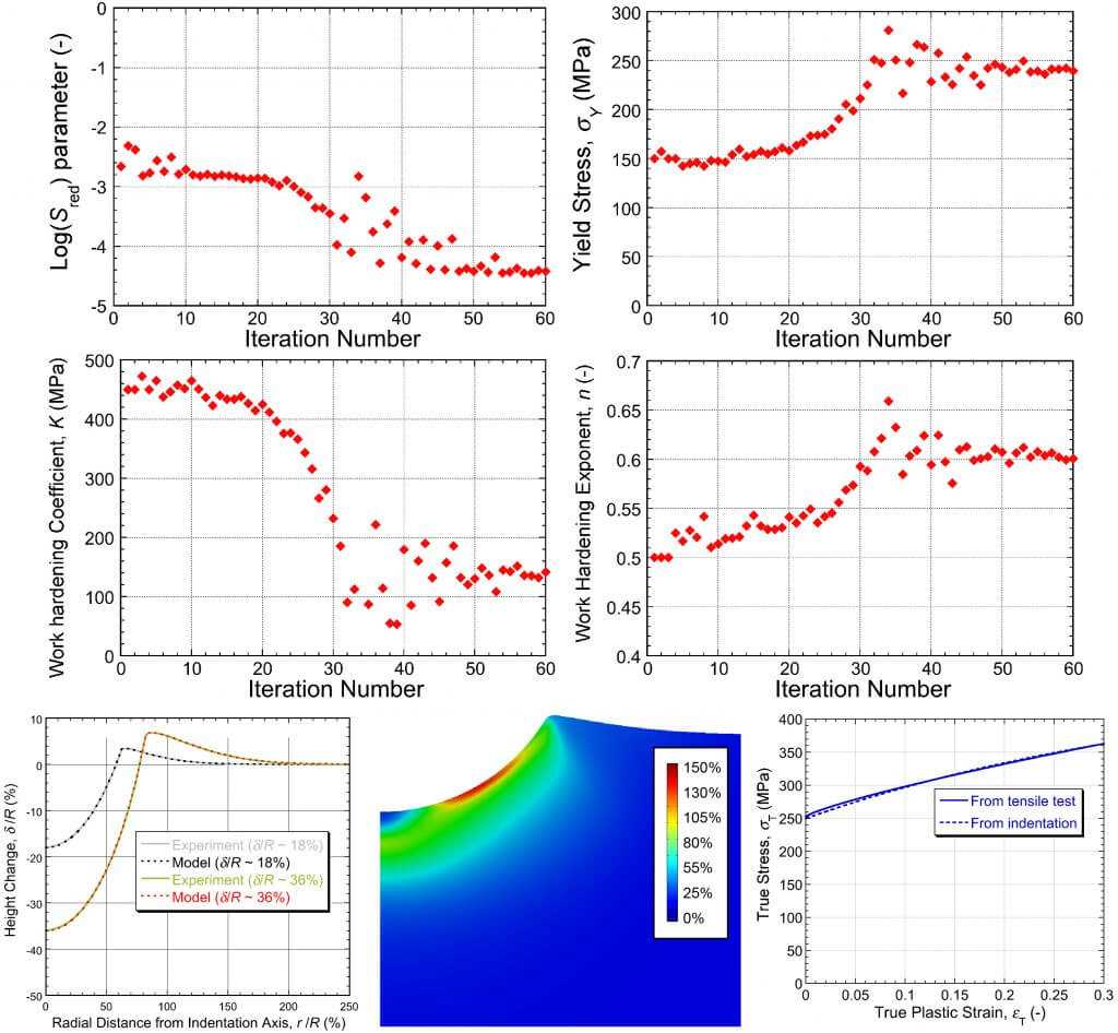
Iterative FEM simulation of the indentation process is central to the procedure. Starting with a trial set of plasticity parameter values, the simulation is run (to the load that was used in the experiment). A comparison is then made between predicted and measured residual indent profiles. The outcome of this comparison is characterised by the value of a misfit parameter. This is zero for perfect fit, but any value below about 10‑3 represents good agreement. A convergence algorithm is used to sequentially select parameter value sets that give improved agreement, until a stable (best fit) combination is obtained. In the Plastometrex software, generically termed “Software for the Extraction of Material Properties from Indentation Data” (SEMPID), this convergence operation has been optimised in a number of ways, such that it is normally completed in a matter of seconds.
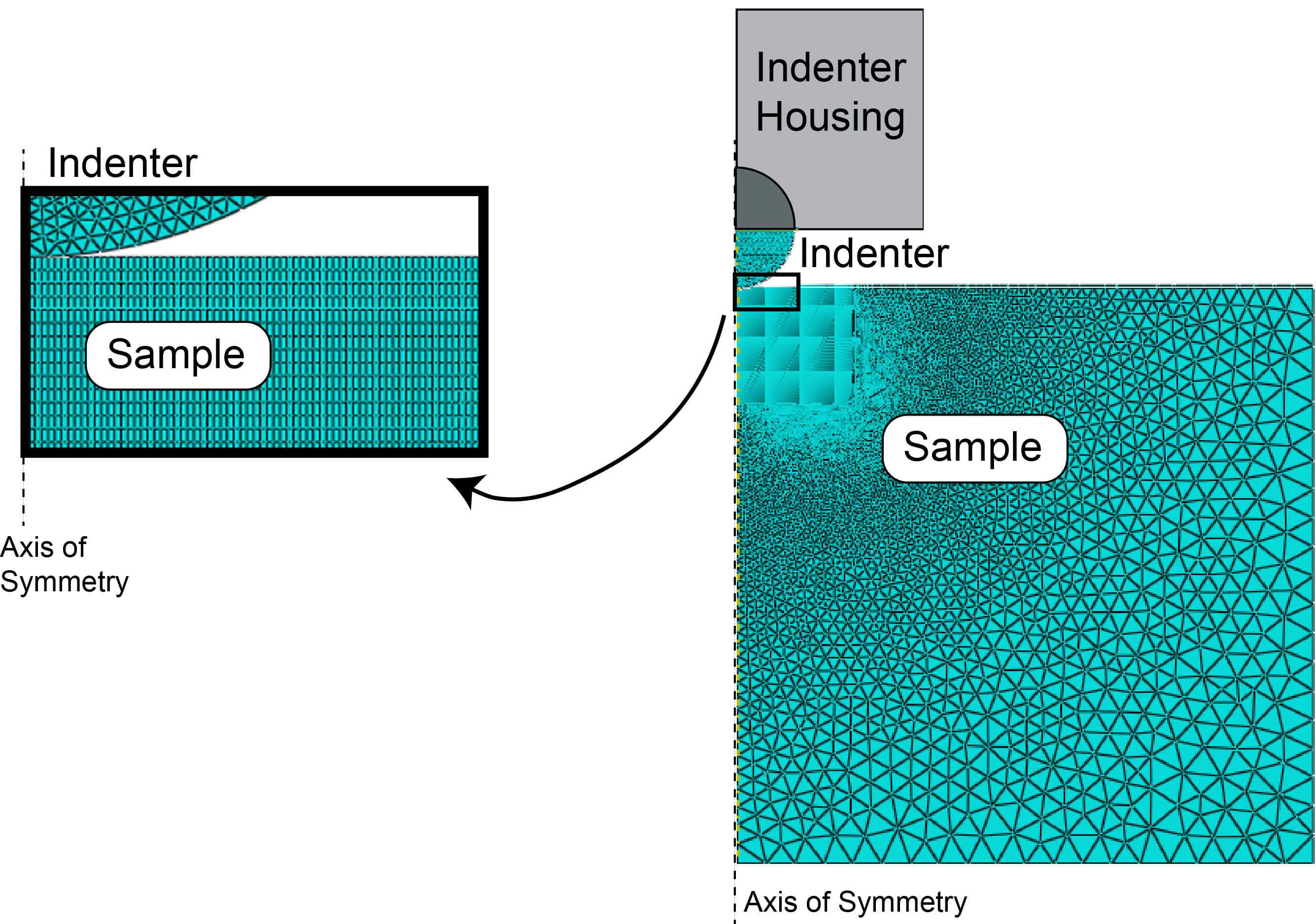
The FEM computations take place fully within the internal operations of SEMPID, so the Plastometrex user need have no FEM knowledge or background. Accuracy and numerical stability are important in these computations, so the meshes used within SEMPID are fine ones – see Fig. 1. A spherical indenter offers many advantages, including the fact that a 2-D (radially symmetric) mesh can be used. The process is scale-independent, so the same computations can be used with a range of indenter diameters. It is, however, important that the volume of the sample being deformed should be large enough to respond mechanically in a way that is representative of the bulk and a typical indenter diameter is of the order of a mm or two. The size and shape of the sample is not relevant, provided it has a flat upper surface, is being supported along its lower surface and it is large enough so that there are no edge effects: in practice, this requires its thickness to be at least about 4 or 5 times the depth of indenter penetration and its width to be at least a similar multiple of the indenter radius.
Since the Plastometrex control software ensures that indentation is carried out to an appropriate depth and applied load, and measurement of the residual indent profile takes place automatically, the operation is very simple from the user’s point of view. Operations of the type illustrated in Fig.2 take place very quickly and the outcome (a true stress – true strain plot, plus an indication of the goodness of fit that was obtained) is provided in less than a minute. Also available are options to carry out further FEM runs, for example to see the stress and strain fields created during indentation.
How are nominal stress-strain curves and UTS obtained?
A plot of true stress v. true strain does fully capture the plasticity characteristics of the material (insofar as this can be done using constitutive laws), but there is a further option available within SEMPID. This is to carry out an FEM simulation of the tensile test, using these plasticity characteristics, so as to produce a nominal stress v. nominal strain curve – ie the raw data obtained from a conventional tensile test. An example of the outcome of this (for the case shown in Fig.2) can be seen in Fig.3 for tests conducted on a work-hardened copper.

It can be seen that the curve is captured well up to the onset of necking (and hence the Ultimate Tensile Strength, usually taken as the peak of a nominal stress v. nominal strain plot, is also reliably obtained). After that point, the predicted curve is unlikely to match the tensile-derived one very closely. This is because, beyond that point, the measured value of the nominal strain is no longer meaningful – most of the extension is taking place within the expanding neck, where local strain levels are becoming very high. Neither the apparent nominal stress nor the apparent nominal strain at the point of final rupture are in reality of any significance (and are unlikely to be accurately reproduced in further tensile tests).
Frequently Asked Questions
What is indentation plastometry?
Indentation plastometry is a method for obtaining a complete true stress-strain curve from an indentation experiment. Unlike a hardness test, which extracts only the indent diameter, it measures the full residual indent profile, gathering data on yield strength, ultimate tensile strength, work-hardening behaviour, and uniform elongation.
Why isn't a true stress-strain curve straightforward even from tensile testing?
Converting nominal stress and strain to true values assumes the sample deforms uniformly along the gauge length. In tension, necking can begin early and unseen, invalidating that conversion. In compression, friction at the interfaces causes barrelling, which also invalidates the standard procedure. There is an FEM-based way to correct for both, but it's rarely applied in practice, so necking and friction are often simply ignored.
How does the iterative FEM procedure work?
It starts with a trial set of plasticity parameters and simulates the indentation to the load used experimentally. It then compares the predicted and measured residual indent profiles using a misfit parameter, which is zero for a perfect fit, with values below about 10⁻³ representing good agreement. A convergence algorithm repeatedly selects improved parameter sets until a stable best-fit combination is reached, normally in seconds.
What sample size and shape does indentation plastometry need?
The size and shape of the sample are largely irrelevant, provided it has a flat upper surface, is supported underneath, and is large enough to avoid edge effects. In practice the thickness should be at least about 4 to 5 times the depth of indenter penetration, and the width a similar multiple of the indenter radius. A typical indenter diameter is one or two millimetres, and the process is scale-independent.
Can indentation plastometry give a tensile UTS?
Yes. From the true stress-strain curve, the software can simulate a tensile test to produce a nominal stress-strain curve, the raw data a conventional tensile test would give. This captures the curve well up to the onset of necking, so the ultimate tensile strength, taken as the peak of the nominal curve, is reliably obtained. Beyond necking the predicted and measured curves diverge, because nominal strain is no longer meaningful once deformation localises in the neck.

